
The Electrical Settings are used for the Add Electrical Rough-Ins, Add Electrical Connection Points, and Connect Rough-In tools. All Settings are saved to Revit project files when Revit is saved.
Each of the Settings tabs have been separated into their own user manual.
All of the sections start with Settings Files - Saving, Importing, and Exporting.
Table of Contents
- Getting Started Videos
- Settings Files - Saving, Importing, and Exporting
2.1- Managing your Settings file
2.1.1- Missing Settings Elements
2.2- Saving Settings to a Revit Project - Electrical Settings
- Using the Add Electrical Rough-Ins Tool
4.1- Electrical Filtering - Rough-Ins & Connection Points
4.1.1- Filtering Schedules with Project Parameters
4.2- Rough-In Placement vs Connection Points Placement
4.3- Restore Default Rules
4.3.1- Default Rough-In Rules & 3D Rough-In Families
4.3.2- Default Connection Point Rules & Generic Annotation Families
4.4- Creating a New Rule
4.5- Configure Rule Conditions
4.6- Additional Conditions
4.7- Deleting a Condition
4.8- Deleting a Rule
4.9- Rearranging the Rule Hierarchy
4.10- Rough-In Placement
4.11- Placement Options
4.12- Selected Placement Location
4.13- Show Rotated Symbols When Sideways
4.14- Rule Combinations
4.15- Creating Electrical Rough-In Families - Using the Add Electrical Connection Points Tool
5.1- Selecting a Connection Point
5.2- Connector Conditions (Optional)
5.3- Connection Point Placement - Using the Connect Rough-Ins Tool
6.1- Selecting a Wiring Linetype
1. Getting Started Videos
2. Settings Files - Saving, Importing, and Exporting
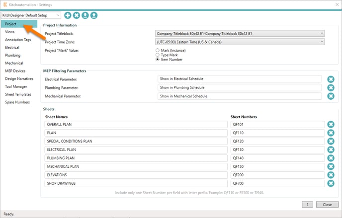

To begin click on the Settings button.
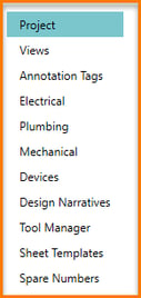
On the left side of the window is your navigation menu, you can click on the vertical list of topics to open a specific Settings tab.
Each tab contains a subset of settings that are used by one of the many KitchDesigner ribbon tools.
The Settings button opens to the Project tab.
2.1- Managing your Settings file

At the top of the Settings window is the Settings Toolbar. This contains the Settings file name and (4) buttons to help you manage your Settings file.
There are occasions where changes in KitchDesigner Settings may need to be distributed to a team of users or you may just want save a backup, in these occasions you can use the Settings toolbar to export settings to other users that can then import them.
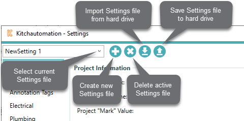
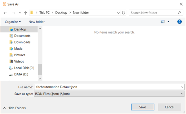
![]() Export Settings files as JSON files and save them to your hard drive.
Export Settings files as JSON files and save them to your hard drive.
![]()
Import Settings files by selecting them using the file browser.
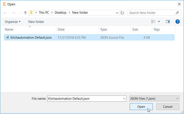
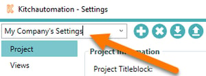
Settings files can also be renamed by clicking on the text to reveal a cursor.
2.1.1- Missing Settings Elements
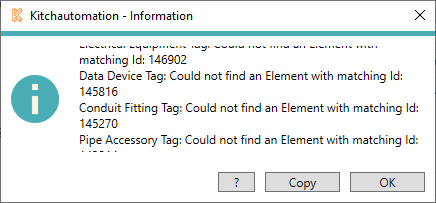
Many of the settings are just links to Revit families and elements in your Revit project, if you import a Settings file into a Revit project that does not also contain these families then those links will be broken and you will receive a Error Message that explains which families were missing. You can copy this list to your clipboard using the Copy button.
2.2- Saving Settings to a Revit Project
A key feature of Settings is that when a Revit project is saved, the active Settings file is also saved to the Revit project file at the same time. This essentially binds the KitchDesigner settings to the Revit project file after each Save.
If the same Revit file is opened by another user on a different computer, all the settings will be just as they were when the Revit project was last saved.
In context of a Revit template file, once you have configured your company settings all you need to do is save your Revit template file and your Settings will also be saved. Any future user of this template will have their Settings pre-configured for their use without ever having to open Settings.
This works great for new projects but for all of your existing projects you will still need to use the Import and Export Settings buttons on the Settings toolbar.
3. Electrical Settings
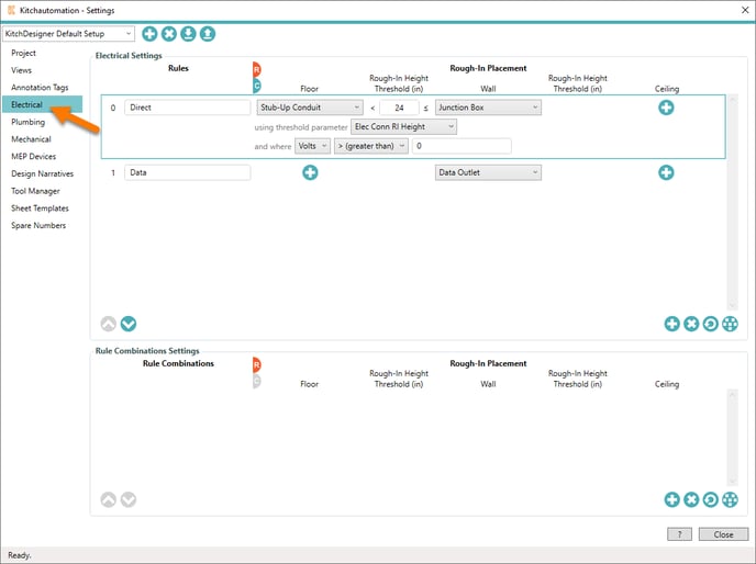
The Electrical tab is where you configure the Add Electrical Rough-Ins, Add Electrical Connection Points and Connect Rough-In tools.
4. Using the Add Electrical Rough-Ins Tool
 Click on the Add Electrical Rough-Ins button.
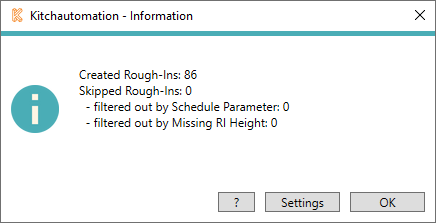
A prompt will appear letting you know how many new electrical rough-in families were created and how many were skipped.
Rough-In families can be skipped for the following reasons:
- When using the MEP Filtering parameters for Electrical on the Project tab. (See Electrical Filtering below).
- When the equipment families are missing the RI Height parameter specified in the rule (Industry Shared Parameters).
4.1- Electrical Filtering - Rough-Ins & Connection Points
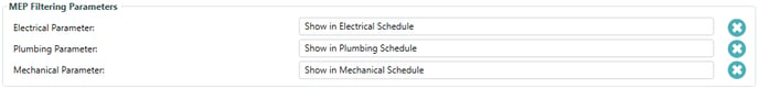
MEP Filtering Parameters is a KitchDesigner feature used to limit some of the families that can receive Electrical, Plumbing, or Mechanical Rough-Ins & Connection Points.
They are also used to limit the same families from appearing in Design Narratives.
To set up and access the built-in filtering, create a project parameter for your equipment families and specify this parameter in these MEP Filtering Parameters.
The KitchDesigner default parameter names are:
- Electrical - "Show in Electrical Schedule"
- Plumbing - "Show in Plumbing Schedule"
- Mechanical - "Show in Mechanical Schedule"
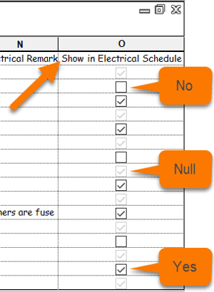
Here is how it works, add a Yes/No project parameter to your equipment families and place that same parameter in the KitchDesigner MEP Filtering Parameters.
Once you have the project parameter created, you can then uncheck this parameter for each family that you do not want to receive rough-ins or connection points from the Add Rough-In and Add Connection Point tools. For example, when the equipment is existing and not new, it doesn't need a new set of MEP rough-ins or MEP connection points.
4.1.1- Filtering Schedules with Project Parameters
You can also include these parameters in your schedules and use them to filter specific equipment out of your schedules.
Create a Filter in your schedule like this:
"Show in Electrical Schedule" does not equal No
"Show in Electrical Schedule" equals Yes is problematic due to the default state of the Yes/No project parameters in Revit which is null, not Yes. (grayed out Yes/No parameters evaluate to null).
To learn more about schedules and the MEP Filtering Parameters, check out our free tutorial Kitchautomation Tutorial 10 - Create MEP Schedules
4.2- Rough-In Placement vs Connection Points Placement
![]() Each Rule contains a Rough-In Placement section and a Connection Points Placement section. We show them separately in our manuals for clarity but they are actually shown side-by-side in Settings.
Each Rule contains a Rough-In Placement section and a Connection Points Placement section. We show them separately in our manuals for clarity but they are actually shown side-by-side in Settings.
Rough-In Placement
Connection Points Placement
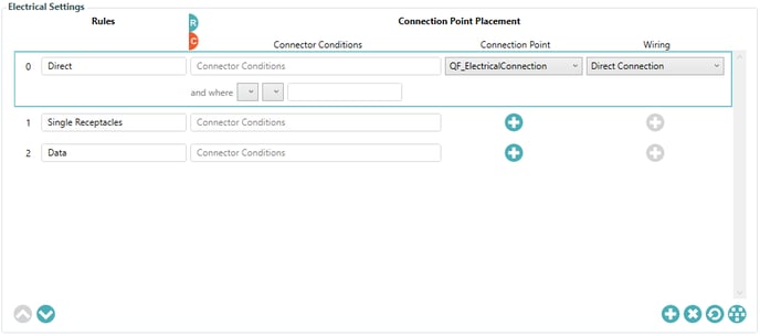
The Electrical Settings consist of a rule based system for Rough-In and Connection Point placement. Users can create their own rules to place any family of their choosing.
Rules consist of:
- Each Rule can contain a Rough-In section, a Connection Point section, and a Wiring linetype.
- Rules are created using logical operator Rule Conditions that use the Industry Shared Parameters
- Optional Connector Conditions can be used in conjunction with pipe connectors inside the equipment families
- Rough-In Height thresholds determine if a Floor, Wall, or Ceiling rough-in will be placed
- There are (6) different placement locations available for each rough-in and each connection point.
4.3- Restore Default Rules
KitchDesigner offers a full set of Default Rules for Rough-Ins or Connection Points that can be loaded into your project. Default Rules also load the symbols that they place into your model.
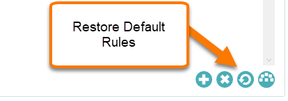
![]() First, click the Restore Default Rules button.
First, click the Restore Default Rules button.
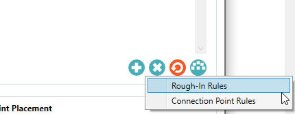
Next you will be prompted to select either Rough-In Rules or Connection Point Rules.
4.3.1- Default Rough-In Rules & 3D Rough-In Families
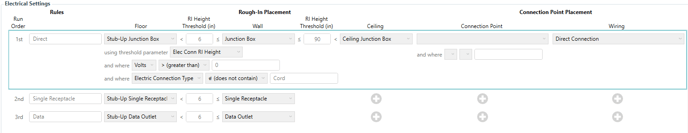
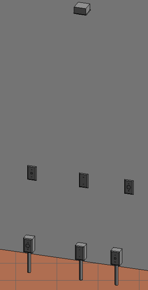
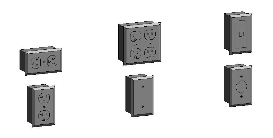
Select Rough-In Rules to load electrical rough-in Rules into your Electrical Settings.
These Rules include junction boxes, single receptacles and data outlets.
Each Rule also loads 3D families for floor, wall, and ceiling rough-ins into your model.
These Rules use Volts, Electric Connection Type, Electrical Remarks, and Elec Conn RI Height parameters.
The electrical rough-in families that are loaded are Electrical Fixture families.
The RI height that is displayed next to each family can be turned off using the Show RI Height parameter in each RI family.
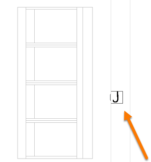
The "J" symbol in the Junction Boxes will be rotated when placed sideways to always stay upright using the Show Rotated Symbols when Sideways setting in Placement Options. (See 5.13)
4.3.2- Default Connection Point Rules & Generic Annotation Families
Select Connection Point Rules to load electrical connection point Rules into your Electrical Settings.

Each Rule also comes with a Generic Annotation family that will be loaded into your model.
These Rules use the Volts and Electric Connection Type parameters.
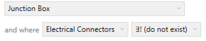
Connection Point Rules are split into (2) types, one Rule to handle Specialty Equipment families with Electrical Connectors and another Rule to handle Specialty Equipment families without Electrical Connectors.
4.4- Creating a New Rule
Click the ![]() in the bottom right corner of the Electrical Settings group to create a new rule.
in the bottom right corner of the Electrical Settings group to create a new rule.
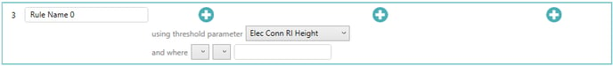
Give your rule a name by replacing "Rule Name" in the text box.
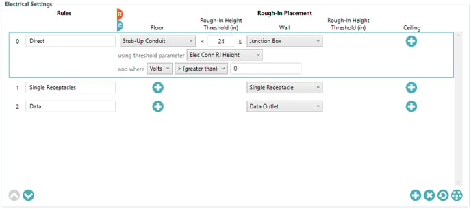
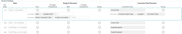
4.5- Configure Rule Conditions
First click a rule to select it to reveal the conditions. Selected rules have a teal outline.
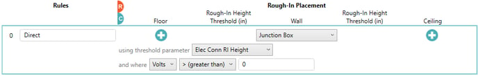
The first step is to choose the RI Height threshold parameter for the Rule.
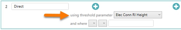
For Electrical, the only choice is Elec Conn RI Height. This is the parameter that will be used to determine whether a Floor, Wall, or Ceiling rough-in is placed.
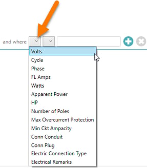
Next configure your first condition using the dropdowns:
Select an Industry Shared Parameter from the first downdown.
Next select a logical operator from the second dropdown.
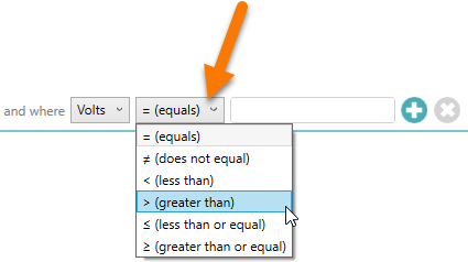
When a number-based shared parameter is selected, the logical operators will resemble math operations.
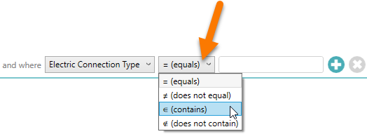
When a text-based shared parameter is selected, the logical operators can be used to match exact text or they can search text and evaluate based on what is contained.
Finally specify a value in the text box to be evaluated with your logical operator.
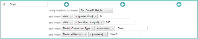
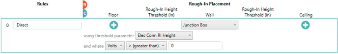
This condition is complete. This rule will now evaluate all equipment families and whenever an equipment family contains the Volts parameter with a value greater than 0, it will pass and move on to the placement section.
4.6- Additional Conditions
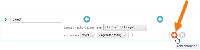
Each rule can contain as many conditions as you would like.
To add an additional condition, hover your mouse over the right end of your last condition to reveal an Add Condition button.
Click this ![]() to add another condition.
to add another condition.
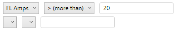
Configure your additional condition and repeat as necessary.
Options are endless and creativity is encouraged.
4.7- Deleting a Condition
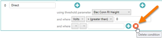
Deleting a condition is similar to adding one, hover your mouse over the right end of the condition you want to delete to reveal a Delete Condition button.
Click the ![]() to delete the condition.
to delete the condition.
Conditions can only be deleted when a rule has more than one, otherwise the Delete Condition button will be inactive. ![]()
If you create a condition that you must remove and it is the final condition of a rule, then you can create another condition as a workaround to activate the ![]() of the condition you want to delete.
of the condition you want to delete.
4.8- Deleting a Rule
Select a rule by clicking it and then you can use the ![]() to delete it.
to delete it.
Selected rules have a teal outline.
4.9- Rearranging the Rule Hierarchy
Rules can be moved up and down using the arrow buttons.
Rules are evaluated from the bottom up and each equipment family can only receive (1) rough-in of the same family type for each rule.
For example, it is possible to create (2) rules that place a "Junction Box" family. If the rule that is evaluated first is successful for a particular equipment family, then that equipment family would not receive a 2nd "Junction Box" family even if the 2nd rule also evaluated successfully. This means you could create a blanket rule such as Volts > 0 as a last line of defense if by happenstance your more specific rules are unsuccessful. This only works when the exact family type is set to be placed in both rules.
4.10- Rough-In Placement
Once the conditions are complete, specify the rough-in families to be placed.
Electrical rough-in families can be from the following categories:
- Electrical Fixtures
- Electrical Equipment
- Conduit Fittings
- Data Devices
Each rule can receive between (0) and (3) rough-in families to be placed.
To specify a Floor, Wall, or Ceiling family, click the ![]() to reveal the family selector dropdown.
to reveal the family selector dropdown.
Families must not be face-based, floor-based, wall-based, or ceiling-based.
Specifying One Family
 Specifying only one family to be placed regardless of which type will result is that family being placed regardless of the rough-in height. The rough-in height thresholds will not even be shown.
Specifying Two Families

Once you specify a second family, the rough-in height threshold will become active. The rough-in height threshold looks at the Electrical Rough-In Height parameter of the equipment family to determine which family will be placed.
In the above example, if the equipment's Elec Conn RI Height parameter is less than 6" then the Floor family will be placed. If the Elec Conn RI Height parameter is greater than or equal to 6" then the Wall family will be placed.
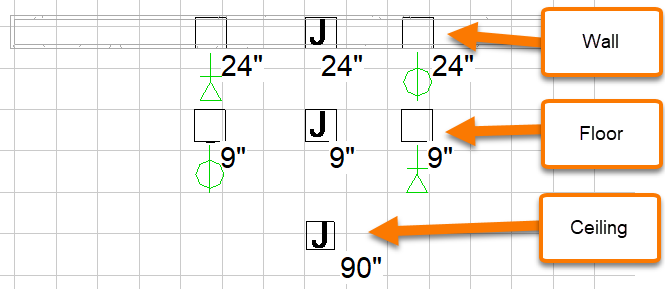
Specifying Three Families

Once you specify the third family, another rough-in height threshold will be active.
In the above example, the Floor family will be placed when the Elec Conn RI Height is below 6", the Wall family will be placed when the RI Height is greater than or equal to 6" and less than or equal to 80", and the Ceiling family will be placed when the RI Height is greater than 80".
No Families

If you only want to place Connection Points, you can skip the Rough-In Placement section and move on to the Connection Point Placement section.
It is important to keep in mind that Conditions affect the entire rule, including both rough-ins and connection points. We will discuss this concept in detail below in the Connector Conditions section.
4.11- Placement Options
When using the Add MEP Rough-Ins or Add MEP Connection Points tools, you can control where each rough-in and connection point will be placed using the Placement Options.
![]() Click the Show Placement Options toggle button to access the placement settings.
Click the Show Placement Options toggle button to access the placement settings.
![]() When the Show Placement Options button is active you can click it again to return to the family settings.
When the Show Placement Options button is active you can click it again to return to the family settings.

![]() Show Placement Options changes all of the family dropdowns into placement indicator buttons.
Show Placement Options changes all of the family dropdowns into placement indicator buttons.
Click on a ![]() button to open the Placement Settings for a particular rough-in.
button to open the Placement Settings for a particular rough-in.
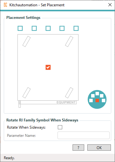
There are three different Placement Settings windows:
One for Floor/Ceiling rough-ins:
Another for Wall rough-ins:
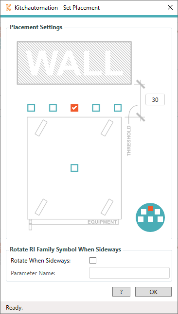
The Wall rough-in placement settings includes a wall image and a threshold dimension.
The THRESHOLD dimension determines whether wall rough-ins placed by this Rule are moved back to be flush with the wall behind the equipment. This field uses inches.
In the above example, if the back of the equipment is less than 30" from the wall then the rough-in will be moved directly back from the selected placement location flush with the face of the wall.
If the back of the equipment is over 30" from the wall then the rough-in will be placed in the selected placement location.
And a third for Connection Points:
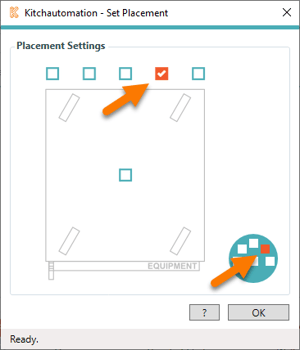
4.12- Selected Placement Location
There are (6) possible placement locations. Each of these locations is represented by a checkbox.
When specifying the Wall rough-in placement, keep in mind that all placement locations will be moved to the face of a wall including the center-center placement.
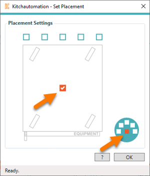
The default placement location is the center-center of the equipment family.
The Show Placement Options icon also shows the selected placement location.
The placement options icons are also visible from the Settings. ![]()
![]()
![]()
![]()
![]()
![]()
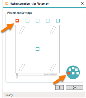
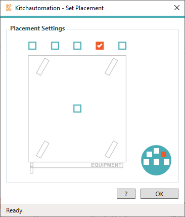
The other locations are back left.
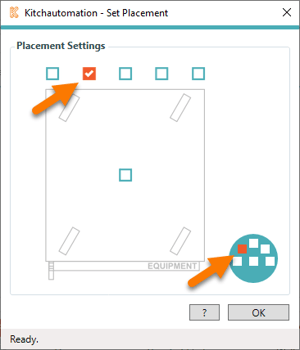
Back center left
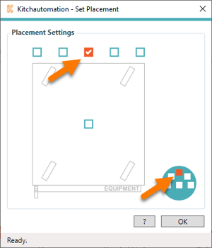
Back center
Back center right
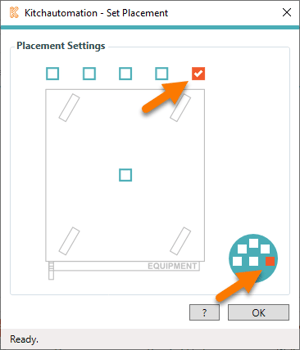
Back right
4.13- Show Rotated Symbols When Sideways
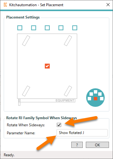
For anybody that uses letters in their rough-in symbols, we have added a special feature to rotate the letter when the rough-in is placed sideways.
To use this feature, add a Yes/No visibility parameter to your rough-in family and specify that parameter in the Rotate When Sideways group of the Show Placement Options window.
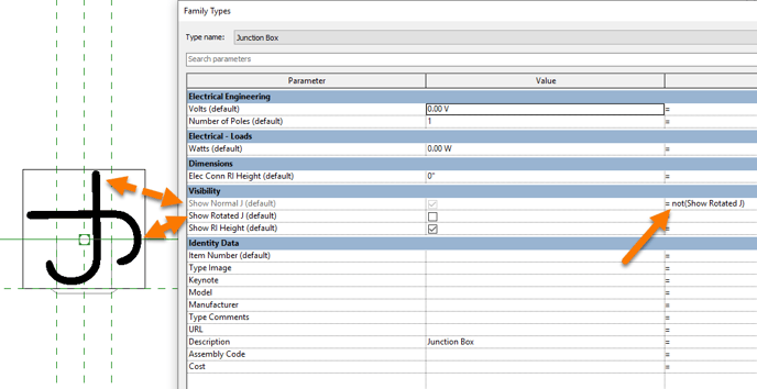
Associate this parameter with a 90 degree rotated letter inside your rough-in family and when a rough-in is placed sideways, the Yes/No parameter will be checked by the Add Plumbing Rough-Ins tool.
The result is your letter symbols always sitting upright.
4.14- Rule Combinations
Rule Combinations are a special Rule that can replace two or more families with a single family when two or more rules pass for a single equipment family.
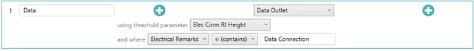
Let's take a look at the Rules above, one rule will place a Junction Box when Volts > 0. The other rule will place a Data Outlet when Electrical Remarks contains "Data Connection".
Now take a look at the Rule Combination below.
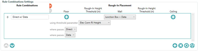
This Rule Combination places a Junction Box + Data family whenever the Direct and Data Rules pass. Those are the same rules from above.
Rule Combinations are a great way of reducing the amount of families that get placed when using the Add Electrical Rough-In tool and result in only one tag getting placed for multiple rough-ins.
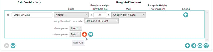
It is possible to add unlimited rules to a Rule Combination and they include Rough-In Height thresholds similar to the Rough-In Rules.
4.15- Creating Electrical Rough-In Families
KitchDesigner requires Electrical Fixture, Electrical Equipment, Conduit Fittings, Data Devices, or Fire Alarm Devices families to be used with the Add Electrical Rough-Ins tool. 3D rough-ins are not required but they are highly recommended. Kitchautomation provides a default set of 3D MEP families when you use the Restore Default Rules button.
If you decide to build the plumbing rough-in families on your own, please read the following tips:
- Adding the Item Number parameter to your Rough-In families is recommended if you use Item Number as your Mark parameter but it is not required. The value of the Item Number parameter is passed to the Rough-In family's Item Number parameter.
- Adding RI Height parameters to your Rough-In families is recommended but not required. The value of the RI Height parameters is passed to the Rough-In family.
- When locking the RI Height parameter to a dimension to control the geometry’s height, remove any reference planes in the Front elevation that are not snapped to the geometry. Offset & RI Height are set based on whether the reference planes in the Front elevation move with the 3D geometry.
- For your wall rough-in families, locate the insertion point in the center (L-R) and at the wall (F-B), the families insertion point will be moved back to the face of the wall so if you had a escutcheon you would set the insertion point at the back of the escutcheon.
- For floor or ceiling rough-in families, locate the insertion point in the center-center.
5. Using the Add Electrical Connection Points Tool
 Click on the Add Electrical Connection Points button
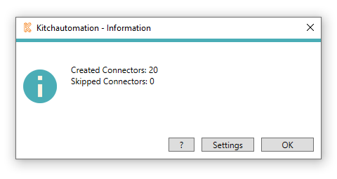 A prompt will appear letting you know how many new electrical connection points were created and how many were skipped.
Electrical Connection Points can be skipped for the following reasons:
- When using the MEP Filtering parameters for Electrical on the Project tab. (See Electrical Filtering).
5.1- Selecting a Connection Point
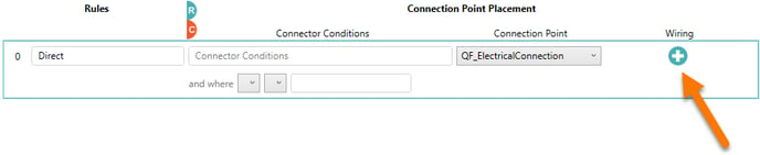
Selecting a Connection Point to be placed by your Rule is done using the ![]() button.
button.
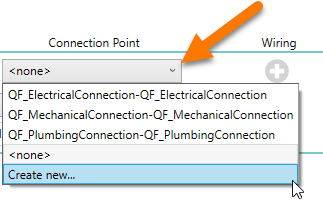 Generic Annotation families can be selected from the dropdown list.
There is also a Create New... option that can be used to create your own Generic Annotation family.
Once you click Create New... the Generic Annotation Creator window will appear.
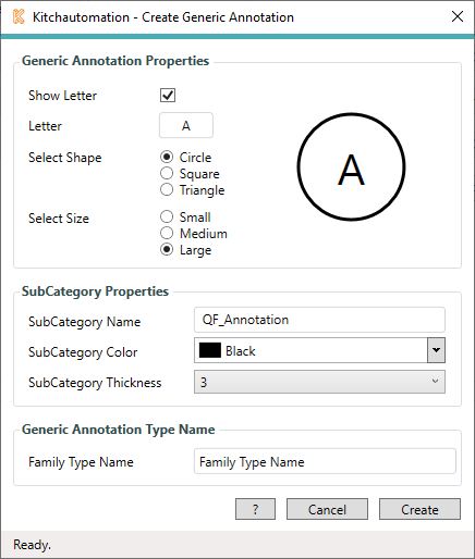
You can create your own Generic Annotation family using (3) different shapes, (3) different sizes, and your choice of (1), (2), or (3) letters in the inside of your shape.
- Small - Approx 4.25" at 1/4" scale and can contain up to (2) letters
- Medium - Approx 6" at 1/4" scale and can contain up to (3) letters
- Large - Approx 7.5" at 1/4" scale and can contain up to (3) letters
Make your selections and to see a preview of what your Generic Annotation will look like. (not to scale)
Specify the SubCategory Name, Color, and Thickness. Subcategories can be accessed from the Object Styles button on the Manage tab in Revit.
Give you new family a unique name and click  to add your new Generic Annotation family to your project.
This newly created family will now be selectable as a Connection Point.
5.2- Connector Conditions (Optional)
It is important to understand that Connector Conditions are not required to place Connection Points. These special conditions are added on top of the Rule Conditions to add an extra layer of differentiation for families that contain connectors.
The benefit of using Connector Conditions is to differentiate families with Electrical Connectors, allowing you to place one type of symbol for certain Electrical Connectors, and a different symbol for other types of Electrical Connectors.
If you just want to place Connection Points on every equipment family where Volts > 0, then you can just leave the Connector Conditions empty and they will act as if they pass for every family. The Add Elec Conn Point tool would then move on to placement and place the specified Electrical Connection Point per the Placement Options.
But it is also possible to leave the Rule Conditions empty and use only the Connector Conditions for your rule. Here is a quick refresher on Connectors so you see what parameters can be used in conditions.
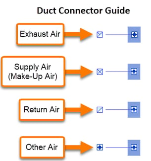
Connector Labels
Although Connectors are inside of families, it is possible to see them from a floor plan view in your project. By clicking on a family to select it you will be able to see the connectors inside of that family.
They don't give you much information about the connector but they labels do show a symbol that can be used to figure out the System Classification.
Here is a handy guide to all of the connector labels:
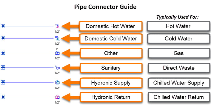
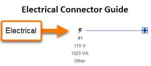
Electrical Connectors
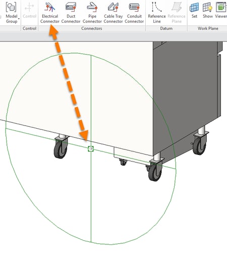
Electrical Connectors can be added to any family using the Electrical Connector button on the Create ribbon. They just need to be attached to an extrusion or other piece of geometry.
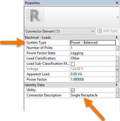 By clicking on the Electrical Connector Element represented by the green circle you are able to see the Connector properties.
Two properties are used by Connector Conditions:
- Connector System Type is a dropdown list that cannot be edited
- Connector Description is a text field that can be edited.
Now let's click to select a rule and reveal the conditions. Selected rules have a teal outline.


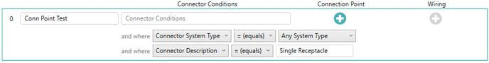
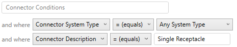
Next configure your first Connector Condition using the dropdowns:
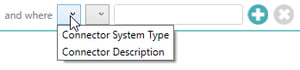
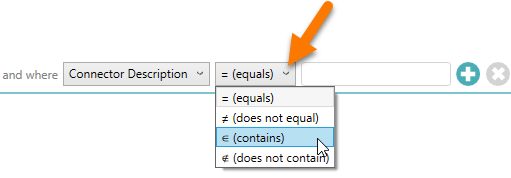
Select either Connector System Type or Connection Description from the first downdown.
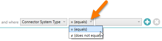
When Connector System Type is selected, the logical operators only include equals and does not equal.
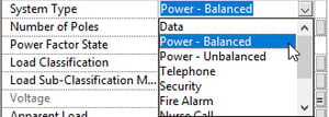
The last step is to specify a Connector System Type from the dropdown. You will notice this list is the same as the list above from the Electrical Connector properties.
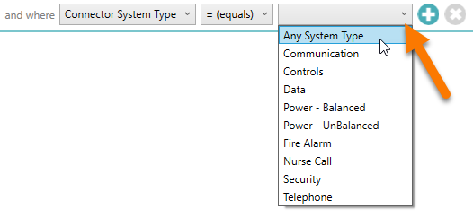
When Connector Description is selected, the logical operators can be used to match exact text or they can search text and evaluate based on what it contains.
Specify a value in the text box to complete this condition.

This rule will now evaluate all equipment families that contain Electrical Connectors. Any Electrical Connector with a Connector Description of "Single Receptacle" would pass and move on to the Connection Point placement.
5.3- Connection Point Placement
 Connection point placement is similar to rough-in placement with one main difference:
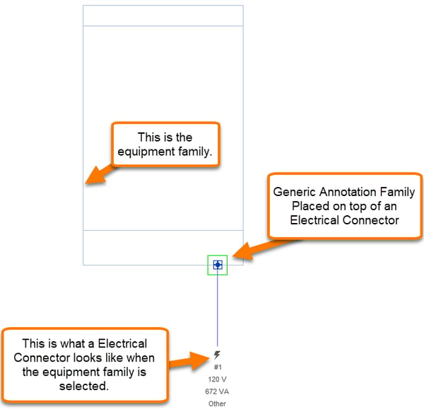
When the family receiving the connection point contains an Electrical Connector, the location of the Electrical Connector will be used in lieu of the placement location.
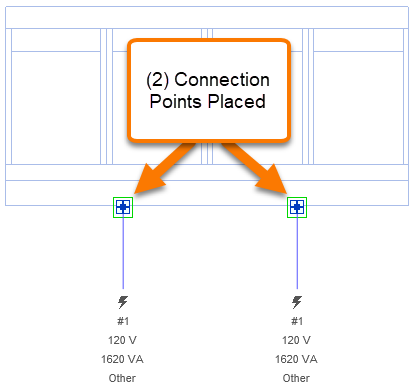
When the family receiving the connection point contains multiple Electrical Connectors, connection points will be placed on top of each Electrical Connector.
6. Using the Connect Rough-Ins Tool

Click on the Connect Rough-Ins button
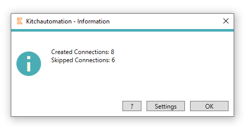
A prompt will appear letting you know how many new Connection Arcs were created between electrical rough-in families and electrical connection points as well as how many were skipped.
Connection Arcs can be skipped for the following reasons:
- When the rough-in is less than 2" from the connection point.
6.1- Selecting a Wiring Linetype
The Wiring setting is a linetype used by the Connect Rough-Ins tool.
The Connect Rough-Ins tool creates an arc between the rough-in and the connection point of the same rule.
To activate the Wiring button ![]() , you must specify at least (1) rough-in and a connection point. Otherwise there is nothing to connect.
, you must specify at least (1) rough-in and a connection point. Otherwise there is nothing to connect.
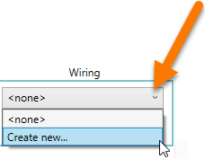
Once you see the ![]() , click it to show the dropdown.
, click it to show the dropdown.
Here you can select a linetype that you have created in your Revit project. Do not use a linetype that is used for anything other than the Connect Rough-Ins tool.
When the Connect Rough-In tool is used, it deletes all lines of the specified linetype and then replaces them with new arcs. For this reason, you should not use this line type for anything else in your project otherwise it will get deleted when you use the Connect Rough-Ins tool.
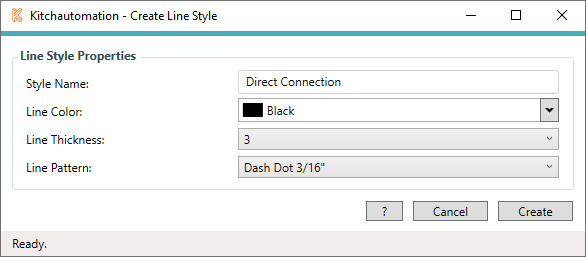
It is easy to create a new linetype using the Create New... option.
Select you linetype style name, color, thickness and pattern.
Click and the new linetype will be added to your Revit project and will be selectable in the Wiring selector.
![]() There are no placement options for the Wiring or the Connect Rough-Ins tool.
There are no placement options for the Wiring or the Connect Rough-Ins tool.